IoT — the Internet of Things — is quite the enduring buzzword, allowing for advanced control and interaction between smart devices. Such interaction often involves “dialing home” to a server, which resides offsite, and that you don’t control.
This kind of setup can be useful, but often you don’t really want company X knowing that you turned your light on 10 times today, or that you took a nap on your connected bed at 1:30 PM on a Tuesday while you were “working” from home. For that matter, if there’s a connection problem — on your end or externally — you still want to be able to activate your appliance. Perhaps most importantly, if company X stops supporting a particular device in the future, or if it goes out of business, you’re probably out of luck.
Tasmota on ESP8266
If you are technically savvy enough to install home or business IoT systems, you’ve also probably considered a few of these risks and drawbacks. The good news is that there is a way to take control of your automation, via the open-source (GPL-3.0) Tasmota alternative ESP8266 firmware. Installing it requires some technical know-how, and according to its about page, “Tasmota is not a commercial product and support is limited.” It also notes that “If you don't have the willingness to tinker and learn... TURN BACK!”
That being said, the process isn’t nearly as challenging as it sounds. This article will walk you through the steps to install on a Sonoff Basic Smart Remote Control WiFi Switch, the general steps for which should be applicable to a wide variety of other ESP8266-based devices. Such modifications are, of course, at your own risk. Never attempt any such operation while plugged in to mains power.
Tasmota Tutorial: What You’ll Need
To make these software changes, you’ll need the following:
· USB to UART converter: Several options will work—a CP2102 -based device was used here. The board needs to break out 3.3V for power. Install drivers as needed.
· Soldering iron/header pins for connection to ESP8266 module: Different hardware will vary, but in the case of the Sonoff Basic, male header pins are a good choice.
Software:
· ESPEasy: Click on the latest release listed here, then scroll down and download the appropriate .zip file, extracting it to your desktop or somewhere else. The file to download should be named something like "ESPEasy_Mega-20200515.zip".
· Tasmota firmware: Scroll down on this page until you find the tasmota.bin file. Download and place it in the newly created ESPEasy directory. Other firmware versions are available in a variety of languages.
· IP Address scanner like Wireless Network Watcher
· Terminal program for troubleshooting: I used the Termite RS232 terminal for this operation, but others should theoretically work. PuTTY was also tried but was not immediately successful.
Connect Tasmota & Sonoff Basic
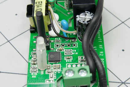
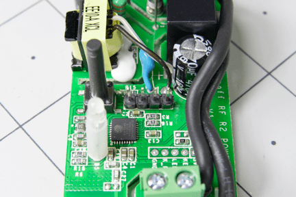
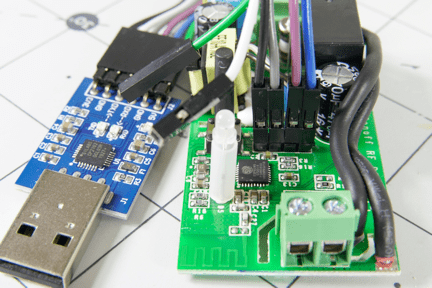
Solder header pins to PCB through-holes as shown
Disassemble the unit. It comes undone very easily with just your hands, as it’ll be secured down later with the wire strain relief screws. There is a set of unconnected through-holes in the middle of the board, to which you’ll need to solder header pins or connection wires. These are conveniently labeled as GND, TX, RC, and 3V3 on the back. Alternatively, you could connect up with pogo pins if you have several to program.
Connect the USB to UART adapter to the Sonoff Basic unit via the soldered headers and jumper wires. Connect ground and 3.3V directly, along with Tx on the adapter to Rx on the Sonoff Basic, and vice versa. Plug in the adapter to your computer’s USB port, with the button held down on the Sonoff Basic to put it in programming mode. Open FlashESP8266 in the ESPEasy directory and select the device’s COM port (check in Device Manager, if needed), along with the tasmota.bin firmware, and press Flash. If all is well, a terminal will pop up showing the software writing progress, and after a minute or so a “Flash Complete” dialog will pop up.
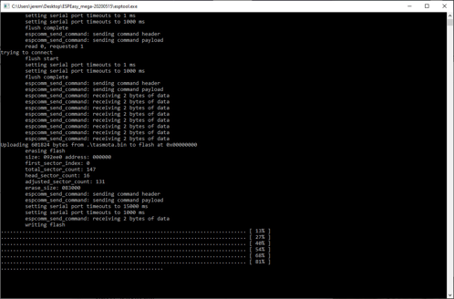
Flashing...
Open your smartphone and check the list of WiFi networks available. If all has gone according to plan, there will be a new network called tasmota… Log on to this network, and you’ll be greeted with a sign-in screen, where you can enter your access point (AP1) SSID and password (both of which seem to be case sensitive). Save this on-screen, and you’ll see the network drop out of sight. Log back on to your main network on your computer, open up your IP address scanner, and there will be a new connected device by Espressif Inc.
Type in the IP address provided by your network scanner to your browser, and you’ll be greeted with a simple page where you can toggle the unit on and off. You can also press the Sonoff’s physical button, which changes the onboard LED and ON/OFF status on the page, but you won’t hear the actual relay clicking until it’s connected to AC power.
Sonoff & Tasmota Switch
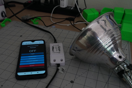
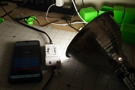
Now that your system is running on your bench or desktop, it’s time to let it actually control something. Place the board back in its housing and loosen the two sets of terminals for line and neutral. Insert wires for your device or extension cord, as appropriate, making sure the line and neutral are not swapped. Tighten these down; then screw in the strain relief clamp device to secure the housing and wires in place.
Plug it in, log onto the device’s IP address, and you can flip the relay remotely with the same interface you used before. Additionally, the physical button on the device also switches the relay—very convenient when you don’t want to take your phone out!
Tasmota Commands: Static IP
If you want to assign a static IP address (so you won’t have to search around to connect up to it), click on the console button on the Tasmota webpage. Enter: ipaddress1 [input your desired IP address] then restart 1 to apply the changes. Commands ipaddress2 and ipaddress3 set the gateway and netmask, which may be helpful depending on your usage.
Tasmota Serial Bridge for Troubleshooting
While static IP commands do work, I got into some weird connection issues a few times after attempting assignment, and had to instead connect up via the Termite serial console. The same sort of commands that work in the online console seem to work here, so it’s a good backup if you can’t connect for whatever reason. A full list of Tasmota commands is found here — reset 1 seems to be especially helpful.
Other Tasmota Configuration Options
Letting the router assign an IP address may be the easiest option, and you can configure it to use MQTT to pass signals around. As explored further here, in the context of using a Raspberry Pi Zero W as a broker, a MQTT setup is able to communicate even if a client’s IP address changes. Beyond the console and simple on/off switches, the graphical web interface provides for a variety of configuration options (including MQTT), so if everything goes well, you may not need to use the console at all!
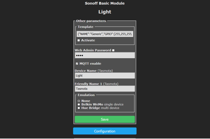
Caption: You can conveniently rename your device or devices.
Sonoff & Tasmota: Customization at Minimal Cost
The Sonoff Basic is a popular and inexpensive choice for using Tasmota alternative IoT firmware, but many other devices can take advantage of it. A vast library of tested devices with usable Tasmota templates is available, including the popular Adafruit Huzzah ESP8266 breakout. While you could write your own firmware for such a device — and I did for this ESP8266-based garage door opener — Tasmota gives you a wide variety of customization tools without reinventing the wheel.


