Clock oscillators have become essential to digital equipment by providing the precisely timed reference signal that controls an electronic circuit. But the application environment for oscillators is continually changing. Designers are demanding smaller units for their portable and wearable products; shorter design cycles call for faster turnarounds for new frequency options; and emerging applications such as 5G require increasingly precise performance.
Although products based on micro-electro-mechanical system (MEMS) technology offer alternatives in some applications, manufacturers of quartz crystal oscillators are responding to these new requirements with a range of new designs.

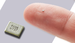
Figure 1: Kyocera’s CX1008 crystal comes in a tiny package for wearable and IoT devices (Image Source: Kyocera)
Quartz Crystals and Quartz Oscillators: The Basics

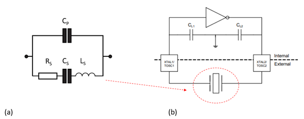
Figure 2: (a) The electrical equivalent circuit of a quartz crystal (Image source: IQD); (b) a crystal oscillator circuit (Image source: Atmel/Microchip)
Figure 2 (a) shows the electrical equivalent circuit of a crystal, consisting of a capacitor in parallel with a series R-L-C combination. Rs, Cs, and Ls represent the piezoelectric contribution and Cp represents the shunt capacitance between the electrodes. The magnitude of Ls depends on the mass of the crystal and Rs represents mechanical losses; the series resonant frequency fs is given by:
![]()

and the quality factor, Q, by:

Figure 2(b) shows the crystal and a drive circuit that consists of an inverting amplifier and a capacitive feedback network. The complete circuit forms a Pierce crystal oscillator. The drive circuit can be packaged with the crystal as a single device or, as shown here, incorporated into a microcontroller and used with an external crystal.
Smaller Packages Affect Crystal Characteristics
The continuing trend towards smaller package sizes in end equipment affects every electronic component, and passives are no exception; there has been a move from leaded to surface-mount packages in successively smaller sizes. With the notable exception of maximum power dissipation and perhaps breakdown voltage, the electrical characteristics of a resistor, capacitor or inductor change little as its size is reduced; this is not true, however, of a quartz crystal.
For a given crystal Q and value of fs, the equivalent series resistance (ESR), Rs, is inversely proportional to the active area of the crystal: smaller crystals have a smaller active area and a higher ESR. In practice the Q for small crystals is not as high as for larger ones; reduced Q also contributes to a higher ESR.
Downsizing from a crystal in a 1210 package (1.2 x 1.0mm) to a 1008 package (1.0 x 0.8mm) would ordinarily increase Rs by approximately 30 percent, requiring a change to the drive circuit design to avoid issues such as inconsistent start‐up performance.
Manufacturers are designing their smallest oscillators to make them easy to use; Kyocera, for example, has optimized its oscillators using its in-house piezoelectric analysis technology to produce a CX1008 quartz oscillator that maintains the electrical characteristics of the conventional CX1210 device. This allows the CX1008 to be incorporated into existing circuit designs without revision.
ADAS and IoT Applications Call for High-Precision Devices
System integrators are continually demanding oscillator circuits with higher precision: Global Navigation Satellite System (GNSS) satellites, for example, are equipped with atomic clocks that utilize internal oscillators to deliver timing measurements accurate to 20 ns.
GNSS signals are used in applications such as automotive Advanced Driver Assistance System (ADAS) technologies, IoT devices, wireless network base stations, and 5G mobile communications. Adding these functions to portable and wearable devices is fueling demand for clock oscillators that offer precise and stable operation over an extended temperature range.
The frequency stability of a crystal oscillator depends on several factors:
A) Initial tolerance, typically defined at 25C with a specified load capacitance
B) The frequency change over temperature
C) Stability over variations in load capacitance
D) Frequency stability over time: i.e. aging
Variations in stability have a range of causes. A change in resonant frequency versus temperature is a function of the angle of the crystal cut versus the lattice structure of the quartz. Aging-related changes may be due to contamination, excessive temperatures, excessive drive signals, and other factors.
Smaller packages also affect stability. With conventional processes and technologies, a crystal unit exhibits higher levels of variation in key electrical characteristics when produced in smaller dimensions. Kyocera minimizes these variations by using a high-precision processing technique called plasma CVM (chemical vaporization machining) during manufacturing. This method uses plasma-generated neutral radicals and a chemical reaction at the surface of an object and provides tight control over quartz crystal surface conditions and thickness. The company’s proprietary semiconductor processing technology ensures extremely accurate external dimensions and minimal RS variation for optimal performance at reduced size.
Quartz crystals for precision applications often include temperature compensation: IQD’s IQXT-260-16, for example, is a temperature-compensated 19.20 MHz device that includes the crystal and an analog application-specific integrated circuit (ASIC) in a 2.5 x 2.0 mm package. The part features a frequency tolerance of ±1.0 ppm and a maximum frequency stability of ±0.50 ppm over its operating temperature range of -30°C to +85°C.
Low Power Consumption Key to Success in Wearable Applications
Low power consumption goes hand-in-hand with small size for portable, wearable, and Internet-of-Things (IoT) applications that rely on battery power. The crystal oscillator drive circuit in Figure 2 (b) must have sufficient gain to operate over the entire operating temperature and voltage range; that said, a low value of CL (the combination of CL1 and CL2) will minimize the oscillator current requirements for a given oscillation voltage. Selecting a crystal with a lower ESR will also lower current consumption.
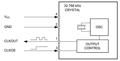
Quartz crystal manufacturers are meeting these challenges with devices that combine low voltage and low current consumption. Micro Crystal AG’s CM9V-T1A, for example, is a 32.768 kHz crystal with ±20 ppm tolerance that combines small size (1.6 x 1.0 x 0.5 mm) with a maximum drive level of 0.5 µW. And the company’s OM-7604 (figure 3), offers typical power consumption of 300 nA together with tight frequency tolerance of ±20 ppm.


Figure 3: The OM-7604 low-power clock oscillator (Image Source: Microcrystal)
Quick-Turn Devices
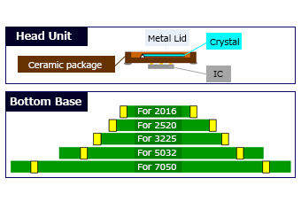
As electronic equipment development cycles grow continually shorter, demand for quick-delivery component samples continues to rise. To meet the demand, Kyocera’s Z-Series clock oscillators use a unique platform structure that combines a fixed size head unit consisting of a quartz crystal, ceramic package and driver IC mounted to a glass epoxy substrate in a variety of standard dimensions. The use of a common head unit reduces lead times by eliminating the need to design the IC, package and crystal elements individually for each standard dimensions. Both standard and low-jitter versions are available. Both types are qualified to the Automotive Electronics Council's reliability standards AEC-Q100 (for ICs) and AEC-Q200 (for passive components).


Figure 4: Kyocera’s Z-series features a flexible two-part design for quick-turn applications (Image Source: Kyocera)
Conclusion
Although quartz crystals and oscillators have a long history, manufacturers are continually refining their products in response to new market demands such as smaller packages or higher performance. Arrow offers a wide selection of products from leading suppliers that can meet all design requirements.


