In a previous article, we discussed Charlieplexing, a small subset of the world of multiplexing. In very general terms, multiplexing occurs when multiple signals are combined to conserve resources. Multiplexing, in this context, allows one to conserve the number of microcontroller IO pins, at the expense of implementing somewhat more complicated hardware and software protocols, such as lighting up a number of LEDs.
Besides complication, the other tradeoff with this type of LED multiplexing is that each LED is only powered for a fraction of the time that it’s nominally “on.” The human eye resolves this into a solid color; however, this can be detrimental to certain video applications, causing flickering and other such anomalies.
Assuming potential flicker is acceptable for your purposes, read on to discover three different LED multiplexing techniques. We’ll start with a basic grid setup, explore using a general purpose 74HC4051 multiplexer/demultiplexer, and finally move on to a MAX7219 LED driver that takes care of things serially.
LED Grid Lights: IO LED Setup
“LED,” of course, stands for light emitting diode. Normally these are used to produce light, but they are also quite functional diodes, allowing current to flow in only one direction. We can take advantage of this behavior to create the grid layout below. Each row is activated by setting IO1 through IO4 high, and columns are activated by setting IO5 through IO8 low.
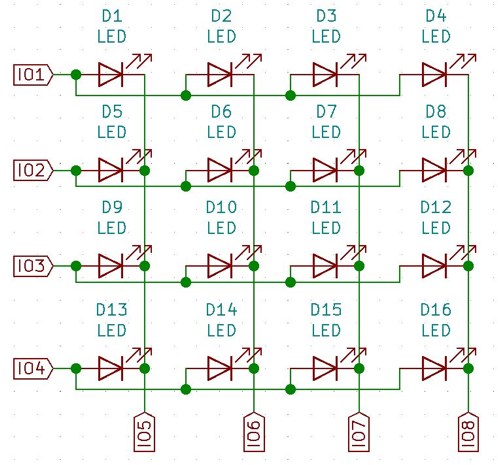
For example, consider the situation where IO1 is set high (with 2-4 low), and IO5 is set low (with 6-8 high). The only path for current to flow is from IO1 to IO5, lighting up LED D1. If IO6 was changed to low as well, D1 and D2 could be powered parallel, and the same would go for D3 and D4, with IO7 and IO8.
As shown, 8 IO control 16 LEDs. The grid could be expanded as needed, controlling a number of LEDs equal to the IO on one axis multiplied by the number of IO on the other. A simple breadboarded example is shown below, controlling a 3x3 matrix of nine LEDs, using 6 IO.
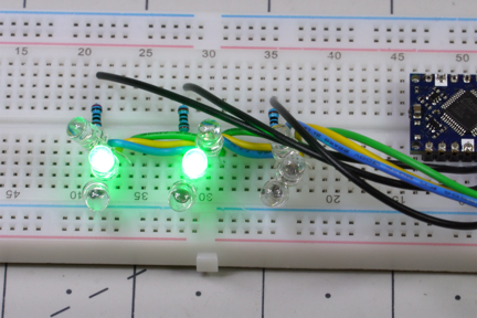
The problem with this technique is that while the LEDs on one row can be controlled easily enough, when column IO are placed into a high state, every LED on that column is turned off. To solve this, each row IO is set high one at a time to activate its set of LEDs. Column IO pins then control which specific LEDs are on. This way, the whole matrix is sequentially activated as needed, a process which is repeated over and over. This happens faster than the human eye can sense, creating what is seen as a constant glow.
This sort of technique can be used in the reverse direction for inputs as well. However, since a button or other sensing device doesn’t normally have a diode as a “bonus,” more parts will be needed.
74HC4051 Multiplexer Chip
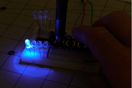
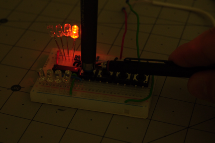
What’s discussed above is useful—and is helpful for understanding how LED multiplexing works—to streamline projects with a multiplexing chip like the 74HC4051. For this chip, three selector inputs—A (pin 11), B (pin 10), and C (pin 9)—create a 3-bit binary number that selects which of its eight output pins will pass along a signal from pin 3.
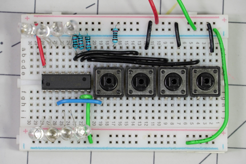
The circuit constructed above shows a manual layout for controlling LEDs with one of these chips. The first button to the left energizes input pin 3 via the blue wire. If none of the other buttons are pushed, all of the select pins are pulled low by a bank of 10K resistors, causing the LED on pin 13 to light up. When the other buttons are pressed, they enable different LED selections, as outlined in the datasheet found here.
For example, if the rightmost selector button is pressed, setting pin 9 high, the LED on pin 1 is illuminated when the button for pin 3 is activated. If, instead, the other two buttons are pressed to set 10 and 11 high, the LED on pin 12 will illuminate with pin 3. As with the LED grid, a microcontroller can make the LEDs cycle faster than the human eye can see.
MAX7219: Arduino LED Multiplexing
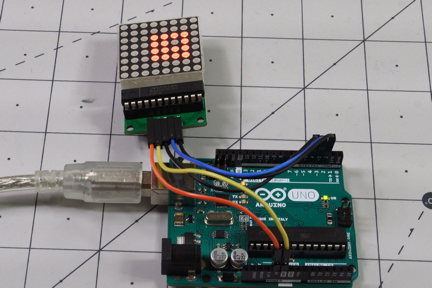
While grid and multiplexer solutions present a number of versatile possibilities, when you simply want to drive a multitude of LEDs from an Arduino or similar, the MAX7219 chip is well suited for the job. This IC receives serial signals from your processor, taking care of actually displaying and multiplexing LEDs without low-level supervision.
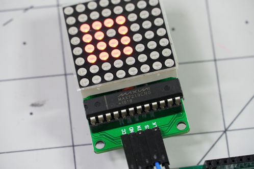
The matrix shown above is an 8x8 grid of 64 LEDS, meaning that an Arduino would theoretically need 16 pins to control it, based on the LED grid method. Here all you need is three control pins, plus the positive and ground lines, and the MAX7219 takes care of the multiplexing without further supervision. This chip is also well-suited for controlling 7-segment displays, with built-in functions for this purpose. Code used to test the display, along with simple LED grid described earlier, can be found on GitHub.
Advantages of Multiplexing Techniques
While the three techniques here are more complicated hardware-wise than simply hooking LEDs up directly to output pins, this ultimately allows you to control many more outputs. This type of setup is normally referred to as “multiplexing,” though one could argue that what we’re doing here is actually de-multiplexing the microcontroller’s signals, as it’s multiplying, not reducing the number of LED outputs. Whatever you call it, it’s a great concept to have in your “toolbox” when needed!
